
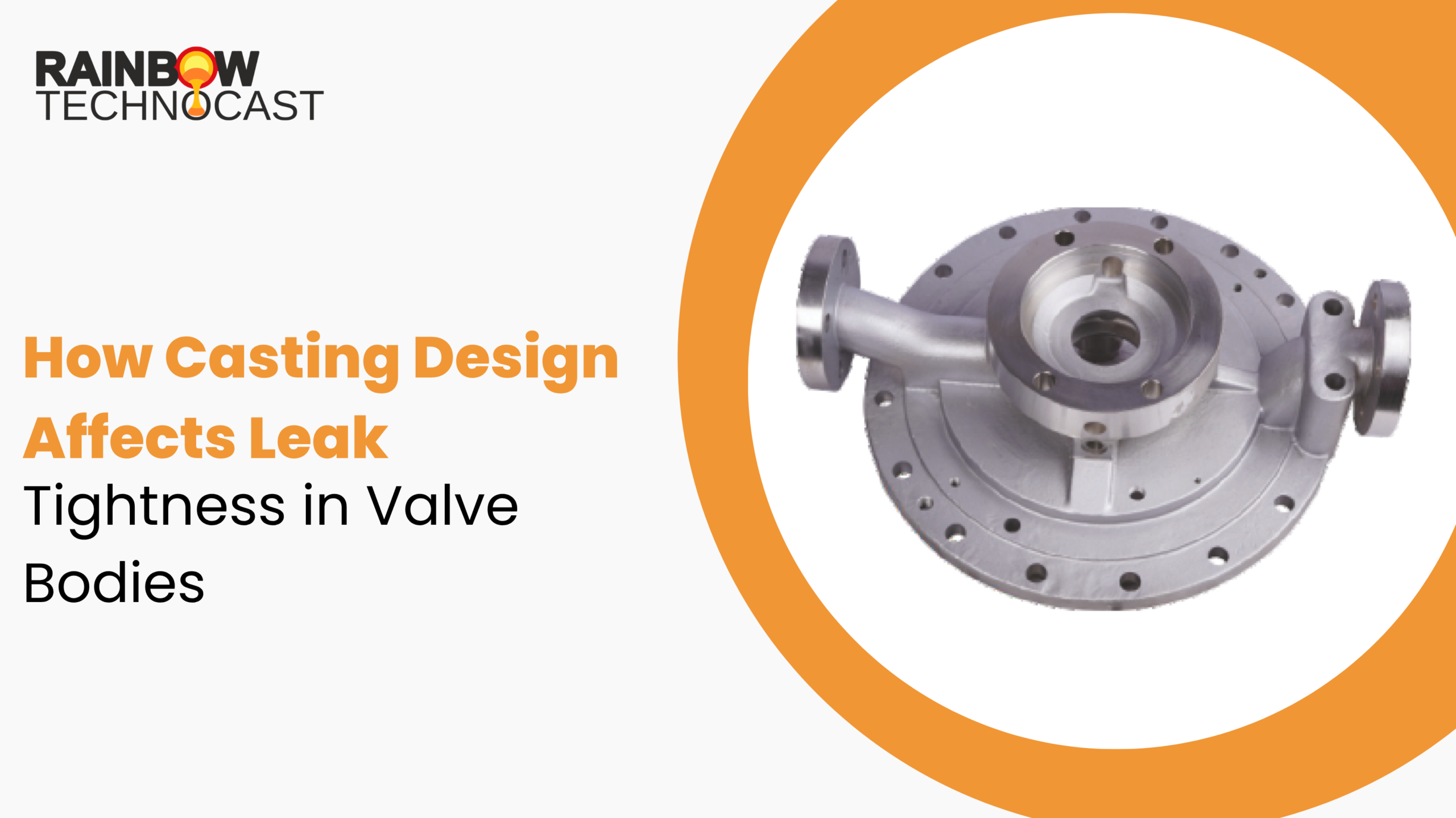
Leak tightness gets treated as a test result. It is actually a design outcome. By the time a body reaches the hydrotest bench, whether it leaks was settled weeks earlier — on the drawing, in the feeding plan, and in the machining allowance somebody assigned without thinking. Bodies that leak almost never leak through solid metal. They leak through a path that solidification created and machining exposed. This piece shows where those paths come from and which drawing decisions prevent them. At Rainbow Technocast we review geometry before tooling for exactly this reason.
Understanding Shell Leakage vs. Seat Leakage
Getting this distinction right saves a lot of misdirected blame.
Shell Leakage
Fluid escaping through the pressure boundary itself — through the wall of the body, not past any seal. This is a casting integrity problem. It is caused by porosity that has linked into a continuous path from bore to atmosphere, by a crack, or by wall thickness reduced below what the pressure demands.
Shell leakage is the foundry’s responsibility, and it is the one this article is mostly about.
Seat Leakage
Fluid passing between the closure member and the seat when the valve is shut. This is a sealing problem, driven by seat design, surface finish, closure geometry, actuator torque and trim material.
Seat leakage is an assembly and design responsibility. A perfectly sound casting can seat-leak, and a porous casting can seal beautifully across the seat while leaking through the wall behind it.
When a valve fails a test, establish which one you have before anyone starts investigating.
How Leak Paths Form in Castings
Molten steel shrinks as it solidifies. The last region to freeze needs liquid metal fed from a riser to make up that shrinkage. If the feeding path closes first, the volume is simply missing, and it stays missing as branching shrinkage porosity in the thermal centre of the section.
Three things then have to happen for that porosity to become a leak:
- The voids link. Individual pores are harmless. Branching shrinkage naturally forms connected networks, which is why it is far more dangerous than round gas porosity.
- The network reaches both surfaces. Often it does not, until machining removes material and opens one end of it.
- Pressure drives fluid through. Cyclic pressure and thermal movement gradually extend and connect the network over time.
That third point explains the most frustrating failure mode in this industry: a body that passed its hydrotest and starts weeping after months of service. Nothing new formed. The path finished connecting.
Design Decisions for Leak-Tight Valve Bodies
1. Wall Thickness Uniformity
The single highest-leverage decision on the drawing. Uniform walls freeze at a similar rate and feed predictably. Varying walls create isolated hot spots, and hot spots produce shrinkage.
The counter-intuitive part is that adding thickness to be safe usually makes things worse. A locally thick region holds more heat, freezes last, and has nowhere to draw from. You added metal and created a void inside the section you were trying to strengthen.
Aim for uniformity first, adequate thickness second.
2. Fillets and Section Transitions
Sharp internal corners do two bad things at once. During solidification they trap heat, creating a hot spot at exactly the junction you needed sound. In service they concentrate stress, so any defect there is loaded hardest.
Rules that work:
- Fillet every internal corner generously — a radius roughly half the adjoining wall thickness is a reasonable starting point
- Taper thick-to-thin transitions over a length of several wall thicknesses rather than stepping them
- Avoid junctions where three or more walls meet at a point; stagger them
3. Boss and Bolt Pad Placement
Bolt bosses and instrument pads are local heavy sections stuck onto thin walls. Left alone, they are reliable porosity sites, and porosity under a bolt boss means a leak path where the fastener tension is highest.
Options, in order of preference: blend the boss into the wall with generous fillets so it has a feeding path; move it to a location that can be fed; or tell the foundry so a chill can be placed. What does not work is drawing it and hoping.
4. Machining Allowance
Allowance is where sound castings get converted into leakers. Too little, and a shifted core or a distortion after heat treatment leaves an unmachined patch on a sealing face. Too much, and you cut deep enough to expose subsurface porosity that would have stayed harmlessly buried.
Assign allowance surface by surface, not globally. Sealing faces get what they need for cleanup plus a defined margin. Non-functional faces get less or none. And agree the minimum wall thickness that must remain after machining, so nobody cuts into the pressure boundary chasing a finish.
5. Parting Line and Core Placement
The parting line and core prints determine where flash forms, where mismatch appears, and where core shift shows up as uneven wall thickness.
Two design points matter for leak tightness:
- Keep the parting line off sealing surfaces and away from critical zones
- Design core prints for positive location. A core with loose support shifts, and a shifted core thins one side of the wall while thickening the other — thin side leaks, thick side goes porous
6. Sealing Surface Design
The gasket face and seat pocket need to be machinable to a controlled finish and stay flat after heat treatment.
- Provide enough stock so the finished face is fully cleaned up
- Keep the surrounding section uniform so distortion during heat treatment is symmetrical
- Avoid placing a heavy boss directly behind a sealing face — that is a hot spot with a machined surface over it
- Specify the surface finish requirement explicitly; gasket seating depends on it
7. Feeding Access
This is the one designers rarely think about and foundries always need. A riser has to physically sit somewhere, connected to the region it feeds, and be removable afterwards without damaging a functional surface.
If the geometry leaves no place to attach a feeder near a heavy section, that section cannot be fed. Involve the foundry before geometry is frozen — moving a pad by a few millimetres on a drawing is free, and it can be the difference between a feedable casting and a chronic one.
How Machining Can Cause Leaks
Worth its own section because of how often it happens.
Subsurface porosity sitting a few millimetres below the as-cast skin is invisible to surface inspection and may be small enough to pass radiography at the specified level. Then the machinist takes a finishing cut across the flange face, opens one end of the network, and a path that was sealed becomes a path that is open.
The casting did not change. The inspection was not wrong. The machining depth reached into a region that inspection had graded as acceptable because it was expected to remain buried.
Two defences:
- Inspect after machining, not only before. Surface NDT on machined sealing faces catches exactly this.
- Design so the last-to-freeze region is not under a machined face. That is a feeding and geometry decision, and it is the permanent fix.
Testing Valve Leak Tightness
- Shell hydrostatic test — the body is pressurised with water to a defined multiple of the class rating, held for a specified duration, with no visible leakage through the wall. The primary shell integrity check.
- Seat test — pressure applied against the closed closure member, with allowable leakage rates defined by the applicable standard and seat type.
- Gas leak test — air or nitrogen, often under water, detects smaller paths than water does because gas molecules penetrate finer networks.
- Helium leak test — the most sensitive option, reserved for high-integrity applications where even trace leakage is unacceptable.
Remember what a water hydrotest can miss. Water surface tension can bridge very fine paths, so a body can pass hydrostatic testing and fail a gas test. If your service medium is gas, test with gas.
Valve Casting Design Checklist
Run this before tooling is cut:
- Are wall thicknesses as uniform as function allows?
- Is every internal corner filleted, with no sharp junctions?
- Are thick-to-thin transitions tapered rather than stepped?
- Is every heavy boss either blended into a wall or flagged for chilling?
- Does every heavy section have a feeding path a riser can reach?
- Is the parting line clear of sealing surfaces and critical zones?
- Are core prints designed for positive location against shift?
- Is machining allowance assigned surface by surface?
- Is minimum post-machining wall thickness stated?
- Are critical zones marked, with NDT method and acceptance level per zone?
- Is surface NDT specified on machined sealing faces after machining?
- Is the leak test medium matched to the service medium?
Twelve questions. Most of them cost nothing to answer at drawing stage and a great deal to answer at the test bench.
Frequently Asked Questions
Can a valve body pass a hydrotest and still leak in service? Yes, and it is more common than people expect. Sub-critical porosity that has not yet formed a continuous path will pass a hydrotest, then link up under cyclic pressure and thermal movement over months of service. Water’s surface tension can also bridge very fine paths that gas would pass through. If the service medium is gas, specify a gas leak test.
Does impregnation fix a leaking casting? Resin impregnation seals fine interconnected porosity and is used routinely on some components. For critical oil and gas pressure boundaries it is generally not acceptable, because it masks a soundness problem rather than correcting it and its durability under pressure and temperature cycling is limited. Check your governing specification before considering it.
What surface finish do sealing faces need? It depends on the gasket or seal type — flat gasket faces, ring joint grooves and soft-seated designs all have different requirements, and the applicable standard specifies them. The important point is to state the requirement on the drawing rather than leaving it to the machine shop’s default.
Is investment casting more leak-tight than sand casting? Investment casting generally produces better surface finish, tighter tolerances and finer detail, which reduces machining depth and therefore reduces the chance of exposing subsurface porosity. But leak tightness is driven by feeding design and section geometry in either process. A well-fed sand casting beats a poorly fed investment casting every time.
Who is responsible when a valve leaks — the foundry or the valve maker? Establish the leak type first. Leakage through the wall is shell leakage and points to casting integrity. Leakage past the closure member is seat leakage and points to trim, finish, torque or assembly. Recording which one occurred, at what pressure and with what medium, resolves most of these conversations quickly.
Conclusion
Leak tightness is designed in, not tested in. Uniform walls, generous fillets, fed bosses, sensible allowances and a parting line kept away from sealing faces do more for it than any inspection scope.
Send us your valve body drawing before the tooling is finalised. We will mark where we expect the last metal to freeze, flag the sections that cannot be fed as drawn, and propose the changes that keep the leak paths out of your pressure boundary.
About Rainbow Technocast
Rainbow Technocast manufactures precision investment cast valve bodies and pressure-containing components in stainless steel, alloy steel and carbon steel. We review geometry and plan feeding before tooling is cut. Our promise: pressure boundaries that hold, verified against a test regime matched to your service medium.
Send your drawing for a design-for-casting review and quotation.